|
|
|
|
|
 |
|
MAXIMUM VERSATILITY AND
PERFORMANCE
|
|
|
|
|
|
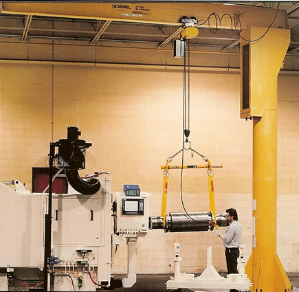
*Our most versatile
crane. Perfect for
underneath traveling cranes, in open
areas where it can serve several work
stations, in outdoor applications such
as loading docks, or in machining and
assembly operations where it can be
overlapped with other jibs to provide
staged operation.
|
|
|
|
|
|
EASE
OF OPERATION |
|
|
|
|
|
|
*Allows operators
to position loads
precisely, effortlessly and efficiently.
|
|
*Precision
tapered roller bearings in top
pivot and trunnion assemblies provide
smooth operation and long life. |
|
*Full
supporting triangular base plate
gussets are used (in lieu of struts) to
minimize crane deflection, thus
making it easier to accurately position
loads. |
|
|
|
|
|
SAFETY |
|
|
|
|
Available
in insert mounted (FS350) and sleeve insert mounted
(FS350S) styles |
|
|
|
|
|
*Head
retaining pin provides the
resistance to accidental upward
dislodgment of the head.
|
|
|
|
|
*Pre-engineered
for use with powered
hoists. A factor of 15% of the jib crane
capacity is allowed for the hoist and
trolley weight with an additional 25%
of the capacity allowed for impact,
thus giving maximum capacity use of
the jib. |
Pricing
and Dimensional Specifications -
Click a Load Capacity Link Here |
|
|
|
|
|
|
|
|
|
|
|
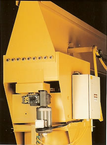
POWER ROTATION |
|
|
Is Optional |
|
|
| FEATURES
OF MOTORIZED CONTROL PACKAGE |
|
|
|
|
|
|
 |
|
|
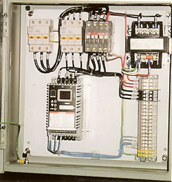
•
Variable Frequency Drive (VFD) is standard. |
|
|
|
The
Variable Frequency Drive can be used in single or multiple speed
applications. |
|
|
|
|
|
|
|
•
Variable Frequency Drive provides the ultimate in load control. |
|
|
|
The
VFD provides the ultimate in load control and positioning from the
slowest possible creep speed up to maximum speed. The VFD is up to
25 times smoother than ballast resistor controls, does not produce
extensive heat, and enables precise starting and stopping. |
|
|
|
|
|
|
|
•
Easily adjustable speed control. |
|
|
|
Through
a simple keypad on the VFD, the acceleration rate,
deceleration rate and rotation speed can be adjusted to fit your application.
This allows you to customize the performance of the jib to your exact
requirements. |
|
|
|
|
|
|
|
•
Designed for indoor and outdoor use. |
|
|
|
When
being used outdoors, the cranes are designed to operate in
winds of 15 mph or less, based on a maximum load surface of 16 square
feet. Consult us for applications exceeding these standards. |
The
direct drive powers the rotation
of the Free Standing Crane. A speed
of 1/2 RPM is standard. |
|
|
|
|
|
|
|
•
Standard NEMA 4X Controls Enclosure. |
|
|
|
 |
|
|
Standard
controls enclosure meets the requirements for NEMA 3R,
12, 4 and 4X environments. Optional enclosures are available for other
environments. |
|
|
|
|
|
•
Low maintenance costs. |
|
|
The
VFD eliminates the need for magnetic reversing contractors,
reduces the number of wearable components in the panel, and reduces
long-term maintenance costs. |
|
|
|
|
|
Pricing
and Dimensional Specifications -
Click a Load Capacity Link Here |
|
|
|
Variable
Speed Controls provide the
ultimate in jib crane rotation control form
creep speed to maximum speed. |
|
|
|
|
|
| STEP
4 - HEAD INSTALLATION |
| TIP:
Trunnion rollers should have full face contact with mast pipe when properly
installed. |
|
|
|
4.1
Wipe protective grease coating off
and/or remove tape from pivot pin. |
|
 |
|
|
4.2
Place and orient tapered roller bearing
inner race (cone) on the mast pivot pin
(diagram 4A). |
|
4.3
Remove safety channel from head
assembly if it is bolted into place. |
|
4.4
Place the head on the mast. Install V-ring seal
(shipped loose) over mast pivot pin and press against
weight bearing frame. Secure head by inserting the
safety retaining pin into the hole located in the
mast pivot pin. Ensure that the safety retaining pin
is centered to within 1/16” inside of the mast pivot
pin. Place 2 hose clamps (one on either side) over
each end of the safety retaining pin and slide them
inward until they come in contact with the mast
pivot pin (diagram 4B). Tighten both hose clamps
such that the safety retaining pin is locked into
place without the ability to slide sideways. Also
ensure that both hose clamps are identically
oriented on the pin and, once tightened, ensure the
clamp screws are facing downward. |
|
|
|
|
Note: It
is imperative that the safety retaining pin
is installed in the “centered” position to avoid a
possible interference with the threaded stud welded
to the weight bearing frame. |
|
|
|
4.5 Reinstall
the safety channel into the head if removed
in step 4.3. |
|
|