|
|
|
|
 |
|
|
• Type IA 300 lbs
duty rated each side
• Made of heavy-wall 6005-T5 aluminum
• Easy to maneuver and maintain
• 5 year warranty
• Adjustable in one foot increments
• Ideal for working over benches and
stadium seating
|
|
|
|
|
|
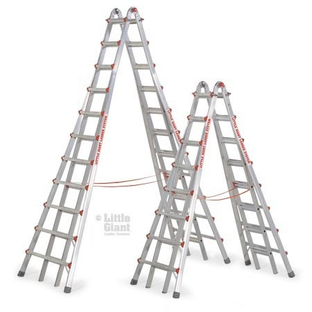
Introducing
the world’s tallest A-frame ladder.
Where other ladders fall short, the Skyscraper from Little
Giant goes above and beyond. The Skyscraper is indeed
the world’s tallest a-frame ladder with a maximum height
of 21-feet, making ceiling-height work simple and safe.
The Skyscraper is perfect
for churches, auditoriums,
gymnasiums and other industrial applications. Plus it’s ideal
for working over benches and stadium seating. And because
it’s portable, the Skyscraper can be used in places where a
motorized lift or bulky scaffolding simply can’t go.
|
|
Safety
The Skyscraper is designed to be the safest ladder on the
planet. Since it’s adjustable, the Little Giant can be used
safely on stairs, ramps, curbs, docks or other uneven
surfaces. |
|
|
|
|
Little
Giant Skyscraper Features:
• Heavy-wall aircraft-grade
aluminum construction
• Rated to hold up to 300 lbs.
• Adjustable for use on stairs, curbs, docks and more
• Perfect for churches, gymnasiums or auditoriums
• Complies with all applicable OSHA ANSI A14.2
standards
• Includes a full 5-year Warranty
|
|
|
Versatility
No other industrial, A-frame ladder gives you the versatility
of a Skyscraper One Skyscraper takes the place of
expensive motorized lifts, bulky scaffolding and flimsy
extension ladders. Plus it’s adjustable for safe use on
uneven surfaces. |
|
|
|
|
|
Little
Giant Skyscraper Configurations: |
|
|
|
|
A-Frame
Ladder
With a simple click of the patented hinge, the Little Giant
can be used as a traditional A-Frame ladder. |
|
|
|
|
|
|
|
|
Staircase
Ladder
Because it’s adjustable in one-foot increments, the Little
Giant allows one side of the ladder to be extended allowing
safe use on uneven surfaces like staircases, curbs or docks. |
Strength
The Skyscraper is made of heavy-wall, 6005-T5
aluminum—the very same material used in aerospace
construction. So it’s ultra-strong while remaining portable.
In fact, The Skyscraper is government-rated to hold up to
300 pounds, so it can handle virtually any industrial
application. |
|
|
|
|
|
90°
Ladder
Traditional ladders make working close to walls nearly impossible. With
the Little Giant, one adjustment allows
you to safely work against any vertical surface. |
|
|
|
|
|
|
|
Operating
Instructions for Little Giant Ladder System®
|
|
|
|
|
|
|
|
|
|
|
|
|
|
|
|
|
|
|
| I.
Description - Skyscraper Telescoping A-Frame Ladder |
|
|
|
|
|
|
|
|
|
|
|
|
|
|
|
|
|
|
A.
Three basic components -The ladder is a telescoping A-frame unit comprised
of three basic components- an inner
ladder unit, which telescopes within two outer units. |
|
|
|
|
|
|
|
|
|
|
|
|
|
|
|
|
|
|
|
1.
The inner ladder unit has a locking center hinge which allows the unit to
be used in the following configurations:
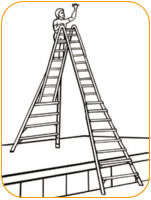
a. A-Frame (See Figure A-1)
b. Staircase (See Figure A-2) |
|
|
|
|
|
|
|
|
|
|
|
|
|
|
|
|
|
|
|
2.
Locking mechanisms on the two outer units of the ladder permit the outer
telescoping sections of the ladder to be
adjusted in length. This lock assembly fits in any rung of the inner ladder,
allowing foot by foot adjustment on either
side of the ladder. |
|
|
|
|
|
|
|
|
|
|
|
|
|
|
|
|
|
|
|
|
|
|
|
 |
|
|
 |
|
|
|
|
|
|
|
|
Figure A-1
A-Frame
|
|
|
Figure A-2
Staircase
|
|
|
|
|
|
|
|
|
|
|
|
|
|
|
|
|
|
|
|
|
|
| B.
The inner and outer side rails are made of aircraft grade aluminum. |
|
|
|
|
|
|
|
|
|
|
|
|
|
|
|
|
|
|
|
1.
There are slip-resistant aluminum rungs on both inner and outer units.
2. Both inner and outer units are finished with slip-resistant feet. |
|
|
|
|
|
|
|
|
|
|
|
|
|
|
|
|
|
|
|
|
|
|
|
 |
|
|
|
|
|
|
|
|
|
|
|
|
|
|
|
|
|
|
|
|
|
|
|
 |
|
 |
|
 |
|
|
|
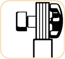
Figure A-3
LOCKED
|
|
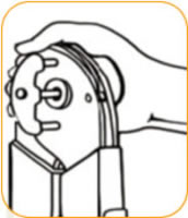
Figure A-4
UNLOCKED
|
|
Figure A-5
SIDE VIEW
|
|
|
|
|
|
|
|
|
|
|
|
|
|
|
|
|
|
|
|
|
| II.
The Little Giant® Telescoping A-Frame Ladder has two mechanical component
parts: |
|
|
|
|
|
|
|
|
|
|
|
|
|
|
|
|
|
|
A.
The HINGE - located at the top of the ladder when it is in storage position,
permits you to alter the shape of the
ladder. The hinge locks in the following position. (See figures A-1, A-2) |
|
|
|
|
|
|
|
|
|
|
|
|
|
|
|
|
|
|
|
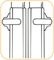
1.
Unlock the hinge by pushing straight in on the palm button until it stays
in the open position on both hinges
(See figures A-3, A-4, and A-5). |
|
|
|
|
|
|
|
|
|
|
|
|
|
|
|
|
|
|
|
|
a.
NOTE- If there is pressure on the hinge lock pins it will make
it difficult to unlock the hinge. To relieve
pressure simply jiggle one half of the ladder back and forth until hinge
lock pins move without force. |
|
|
|
|
|
|
|
|
|
|
|
|
|
|
|
|
|
|
|
|
|
b.
NOTE - DO NOT FORCE HINGE LOCK out with
any tools as it will cause permanent damage to the hinge
mechanism. It should never require more than light pressure to unlock the
hinge if the holes are properly aligned. |
|
|
|
|
|
|
|
|
|
|
|
|
|
|
|
|
|
|
|
2. You
may now open the ladder to the A-frame position by pulling the two ladder
halves apart until both hinge
lock pins snap into the A-frame locked position. (See figure A-1) |
|
|
|
|
|
|
|
|
|
|
|
|
|
 |
|
|
|
|
 |
|
|
|
|
|
|
|
|
|
|
|
|
|
|
|
|
|
3.
To restore the ladder to the storage position, disengage the hinge
locks in the
A-frame position and return the ladder to its storage position. |
|
|
|
|
|
|
|
|
|
|
|
|
|
|
B.
The second mechanical component of the ladder is the LOCK ASSEMBLY.
There are four of these on each ladder. These permit you to change
the height of the
ladder (See figure B-1). |
|
|
|
|
|
|
|
|
|
|
|
|
|
|
| C.
Adjusting the height of the ladder for use in the A-frame position. |
|
|
|
|
|
|
|
|
|
|
|
|
|
|
|
|
|
 |
|
|
|
|
Figure B-1
Lock Assemblies
|
|
|
|
|
|
|
|
|
|
|
|
|
|
|
|
|
|
|
|
|
|
|
|
|
|
|
|
|
|
|
|
1.
With the ladder in the closed, storage position; lay the ladder flat on
an unobstructed surface. (See figure C-1) |
|
|
|
|
|
|
|
|
|
|
|
|
|
|
|
|
|
|
|
2.
Unlock both hinge locks. (See figures A-4 and A-5 on previous page) |
|
|
|
|
|
|
|
|
|
|
|
|
|
|
|
|
|
|
|
3.
With the ladder down on the flat surface, (See figure C-1) pull the two
top lock assemblies out of the rung holes
of the inner ladder and rest them on the side of the outer ladder rail.
(See figures C-2 and C-3) |
|
|
|
|
|
|
|
|
|
|
|
|
|
|
|
|
|
|
|
4.
Telescope top outer unit to desired length. (See figure C-4) |
|
|
|
|
|
|
|
|
|
|
|
|
|
|
|
|
|
|
|
5.
Rotate ladder and place the extended outer unit on flat surface. (See figure
C-5) |
|
|
|
|
|
|
|
|
|
|
|
|
|
|
|
|
|
|
|
|
|
|
 |
|
|
|
|
|
|
Figure C-1
|
|
|
|
|
|
|
|
|
|
|
|
|
|
|
|
|
|
|
|
|
 |
|
|
|
|
|
|
|
|
|
|
|
|
|
 |
|
|
|
|
|
|
Figure C-2
|
|
Figure C-3
|
|
|
|
|
|
|
|
|
|
|
|
|
|
|
|
|
|
|
|
|
 |
|
|
|
|
|
|
Figure C-4
|
|
|
|
|
|
|
|
|
|
|
|
|
|
|
|
|
|
|
|
|
 |
|
|
|
|
|
|
Figure C-5
|
|
|
|
|
|
|
|
|
|
|
|
|
|
|
|
|
|
6.
Telescope remaining outer unit to desired length. |
|
|
|
|
|
|
|
|
|
|
|
|
|
|
|
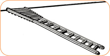
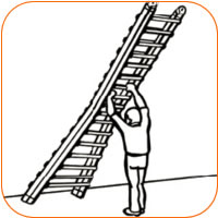
7.
To raise the ladder, brace the feet against the wall and lift the hinged
top; walk (rung by rung) the ladder to a
vertical position. (See figures C-6 and C-7) |
|
|
|
|
|
|
|
|
|
|
|
|
|
|
|
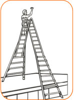
8.
Open the ladder to the A-frame configuration by pulling the ladder halves
apart until the hinges lock into place. |
|
|
|
|
|
|
|
|
|
|
|
|
|
|
|
|
|
 |
|
|
|
|
|
|
|
|
|
|
|
|
|
|
|
|
|
|
|
 |
|
|
|
 |
|
|
|
Figure C-6
|
|
|
|
|
|
|
|
|
|
Figure C-7
|
|
|
|
|
|
|
|
|
|
|
|
|
|
|
|
|
9.
To return ladder to storage position: |
|
|
|
|
|
|
|
 |
|
|
|
|
|
|
|
|
|
|
|
|
a.
In the A-frame position tip ladder to the side and lower to a flat surface. |
|
|
|
|
|
|
|
|
|
|
|
|
|
b.
Unlock both hinges and bring the ladder halves together. |
|
|
|
|
|
|
|
|
|
|
|
|
|
c.
Rotate ladder and place flat on surface. |
|
|
|
|
|
|
|
|
|
|
|
|
|
d.
Reverse procedures of steps C-1 through C-6. |
|
|
|
|
|
|
|
|
|
|
|
| D.
Adjusting the ladder in the staircase position. |
|
|
|
|
|
|
|
|
|
|
|
|
1.
Adjust ladder to desired height. (See steps C-1 through C-5) |
|
|
|
|
|
|
|
|
|
|
|
|
2.
Then adjust side desired for proper alignment to fit the staircase (See
figure D-1). |
|
Figure D-1
|
|
|
|
|
|
|
|
|
|
|
|
|
|
|