| C.
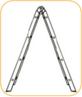
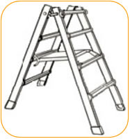
Adjusting the height of the ladder for use in the A-frame position. |
|
|
|
|
|
|
|
|
|
|
|
|
|
|
|
|
|
|
|
|
|
|
|
|
|
|
|
|
|
|
|
|
|
|
|
|
|
1.
Unlock both hinge locks (See figures A-4 & A-5).
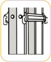
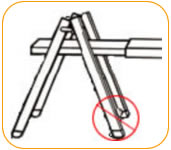
2. With the ladder in the storage position and while holding the inner ladder
assembly firmly in place, pull the four
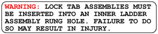
Lock Tab Assemblies out of the rung holes of the inner ladder and rest them
on the side of the outer ladder rail
(See figures C-1).
3. Raise the inner ladder up to the desired height.
4. At the desired height align the outer holes with the nearest rung hole
of the inner ladder assembly. |
|
|
|
|
|
|
|
|
|
|
|
|
|
|
|
|
|
|
|
|
|
|
|
|
|
|
|
|
|
|
|
|
|
|
|
|
|
|
|
|
|
 |
|
|
|
|
|
|
|
|
|
|
|
|
|
|
|
|
|
|
|
|
|
|
|
|
|
|
|
|
|
|
|
|
|
|
|
|
|
|
|
|
|
|
|
|
|
|
|
|
|
|
|
|
|
|
|
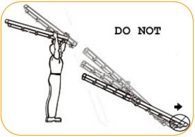
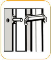
5.
Holding the inner and outer ladder at the aligned height with one hand,
reinsert the opposite Lock Tab Assemblies
into the rung holes with the other hand.
6. Alternate hands and perform the same operation with the other Lock Tab
Assemblies (See figure C-2). |
|
|
|
|
|
|
|
 |
|
|
|
|
|
|
|
|
|
|
|
|
|
|
|
|
|
|
|
|
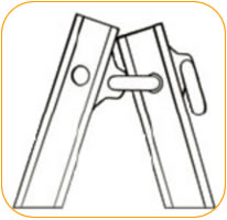
7.
Open the ladder to the A-frame configuration by pulling the ladder halves
apart until the hinges lock into place
(See figure A-2 and A-4).
8. To return the ladder to the storage position, reverse the procedures
and position as seen in Figure A-1. |
|
|
|
|
|
|
|
|
|
|
|
|
|
|
|
|
|
|
|
|
|
|
|
|
|
|
|
|
|
|
|
|
|
|
|
|
|
| D.
Adjusting the height of the ladder in its extension ladder position. |
|
|
 |
|
|
|
|
|
|
|
|
|
|
|
|
|
|
|
|
|
|
|
|
|
|
|
|
|
|
|
|
|
|
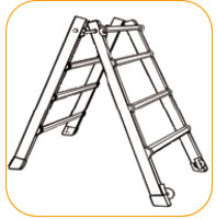
1. From its stored position,
unlock hinge (as indicated in figures A-4 & A-5)
and rotate to extension position until both hinges lock into place.
NOTE: Hinge will first lock in A-frame position, repeat unlocking
hinge to
rotate its extension position. |
|
|
|
|
|
|
|
|
|
|
|
|
|
|
|
|
|
|
|
|
|
|
|
|
|
|
|
|
|
|
|
|
|
|
 |
|
|
|
|
|
|
|
|
|
|
|
|
|
|
|
|
|
|
|
|
|
|
|
|
|
|
|
|
|
|
Figure
D-1 |
|
|
|
|
|
|
|
|
|
|
|
|
|
|
|
|
|
|
|
|
|
|
|
|
|
|
|
|
|
|
|
|
|
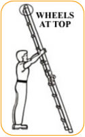
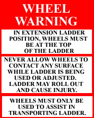
2.
If equipped with wheels, wheels must be at the top of the ladder while
in the extension position. Unlock Lock Tab Assemblies on upper half of
the ladder. Grasp the outer ladder, walk backward, allowing the ladder
to telescope to the desired height. If more height is desired, extend the
lower half of the ladder (see figure D-1). |
|
|
|
|
|
|
|
|
|
|
|
|
|
|
|
 |
|
|
|
|
|
|
|
|
|
|
|
|
|
|
|
|
|
|
|
|
|
 |
|
|
|
|
|
|
|
|
|
|
|
|
|
|
|
|
|
Figure
D-1A |
|
|
|
|
|
|
|
|
|
|
|
|
|
|
|
|
|
|
|
|
|
|
|
|
|
|
|
|
|
|
|
|
|
|
|
 |
 |
|
|
|
|
|
|
|
|
|
|
|
|
|
|
|
|
|
|
|
|
|
|
3.
To store the ladder from its extension position, reverse
the above sequence starting with the lower half of the
ladder. |
|
|
|
|
|
|
|
|
|
|
|
|
|
|
|
|
|
|
|
|
|
|
|
| E.
Staircase Position. |
|
|
|
|
|
|
|
|
|
|
|
|
|
|
|
|
|
|
|
|
|
|
|
|
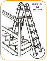
1.
Adjust ladder to desired height (review section
concerning adjusting the height of the ladder for use in the
A-frame position.) If equipped with wheels, the wheels
should be placed on the bottom of the long side, not against
the stairs. |
|
|
|
|
|
|
|
|
Figure
E-1 |
|
|
|
|
|
|
|
|
|
|
|
|
|
|
|
|
|
|
|
|
|
|
|
2.
Then adjust the side desired for proper alignment to fit the
staircase (see figure E-1). |
|
|
|
|
|
|
|
|
|
|
|
|
|
|
|
|
|
|
|
|
|
|
|
|
|
|
|
|
|
|
|
|
|
|
|
|
|
|
|
|
|
|
|
|
|
|
|
|
|
|
|
|
|
 |
|
|
|
|
 |
|
|
|
|
|
|
|
|
|
|
|
|
|
|
|
|
|
|
|
|
|
|
|
|
|
|
|
|
|
|
|
| F.
Scaffolding Trestle Operating Instructions |
|
|
|
|
|
|
|
|
|
|
|
|
|
|
|
|
|
|
|
|
|
|
|
|
|
|
|
|
|
|
|
|
|
|
|
|
|
|
|
|
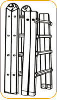
1.
Pull the inner ladder assembly completely out of the outer
ladder bases (see figure F-1). |
|
|
|
|
|
|
|
|
|
|
|
|
|
|
|
|
|
|
|
|
|
|
|
|
|
|
|
|
|
|
|
|
|
|
|
|
|
|
|
2.
Open the inner ladder assembly to the A-frame position until
both hinges lock (See figures A-4 and A-5). This is the first of
two trestles needed for the scaffolding function (see figure F-2). |
|
|
|
|
|
|
|
|
|
|
|
|
|
|
|
|
|
|
|
|
|
|
|
|
|
|
|
|
|
|
|
|
|
|
|
|
|
3.
Grasp both outer ladder bases (see figure F-3). |
|
|
|
|
|
|
|
|
|
|
|
|
|
|
|
|
|
|
|
|
|
|
|
|
|
|
|
|
|
|
|
|
|
|
|
|
|
|
|
|
4.
If equipped with wheels, turn ladder without wheels 180º
and insert lock assemblies of that base into the adjacent holes
of the opposite outer base (see figure F-4). Wheels should be
facing out (see figure F-5). |
|
|
|
|
|
|
|
|
|
|
|
|
|
|
|
|
|
|
|
Figure
F-1 |
|
|
|
|
|
Figure
F-2 |
|
|
|
|
|
|
|
|
|
|
|
|
|
|
|
|
|
|
|
|
|
|
|
|
|
|
|
|
|
|
|
|
|
|
 |
|
|
 |
|
|
|
|
|
|
|
|
|
|
|
|
|
|
|
|
|
|
|
|
|
|
|
|
|
5.
Grasp the outer ladder base with the unused lock assemblies
and lower 1/2 inch, then spread the opposite outer ladder base
to form a second A-frame trestle (see figure F-5 and F-5
Close). |
|
|
|
|
|
|
|
|
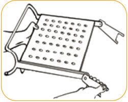
6.
Rotate forked ears on work platform to position indicated
in figure F-6. |
|
|
|
|
|
|
|
|
|
|
|
|
|
|
|
|
|
|
|
|
|
|
|
|
|
|
|
7.
Insert work platform between outer ladder bases on the
third rung down of each base. The wire-formed end of the
work platform should surround the outer rung turned to the
inside of the outer ladder A-frame trestle (see figure F-7). |
|
|
|
|
|
|
|
|
Figure
F-3 |
|
|
|
Figure
F-4 |
|
|
|
|
|
|
|
|
|
|
|
|
|
|
|
|
|
|
|
|
|
|
|
|
|
|
|
|
|
|
|
|
|
|
|
|
|
|
|
|
|
|
|
|
|
|
|
|
|
|
|
|
|
|
|
|
|
|
|
|
|
|
|
|
|
|
|
|
 |
|
 |
 |
|
|
|
|
|
|
|
|
|
|
|
|
|
|
|
|
 |
|
|
|
|
|
|
|
|
|
|
Figure
F-5 Close |
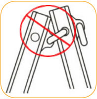
Doing this
step
incorrectly may cause
damage to ladder. |
|
|
|
|
|
|
|
|
|
|
|
|
|
|
|
|
|
|
|
|
|
Figure
F-6 |
|
|
|
|
|
|
|
|
|
|
|
|
|
|
|
|
|
|
|
|
|
|
|
|
|
|
|
|
|
|
|
|
|
|
|
|
|
|
|
|
|
|
|
|
|
|
|
|
|
|
|
|
|
|
|
|
|
|
|
|
|
|
|
|
|
|
|
|
|
|
 |
|
|
|
|
 |
|
|
|
|
|
|
|
|
|
|
|
|
|
|
|
|
|
|
|
|
|
|
 |
|
|
|
|
|
|
|
|
|
|
|
|
|
|
|
|
Wheels should
not be
on inside of trestle |
|
|
|
|
|
|
|
|
|
|
|
Figure
F-7 |
|
|
|
|
Figure
F-5 |
|
|
|
|
|
|
|
|
|
|
|
|
|
|
|
|
|
|
|
|
|
|
|
|
|
|
|
|
|
|
|
|
|
|
|
|
|
|
|
|
|
|
|