 |
|
|
|
|
1.
Remove the ½” bushing taped to the back of the
wiring tray cover and set aside. |
|
|
|
|
2.
Determine mounting location of the temperature
sensor (do not mount at this time). |
|
|
|
|
3.
Choose end of the wiring tray that the sensor will
exit the air curtain based on the mounting location
from Step 2. |
|
|
|
|
4.
Locate the 1/8” hole on the wiring tray next to the
electrical knockout on the side determined in Step 3. |
|
|
|
|
5.
Drill out the 1/8” hole to ½”. |
|
CAUTION:
DO NOT DAMAGE EXISTING
WIRES IN THE WIRING TRAY WHEN
DRILLING |
|
|
|
|
6.
Maneuver the tip of the temperature sensor from
the inside of the wiring tray out through ½”
hole. |
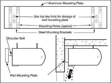
| FIGURE
5 - Wall Mounting Plate Storage |
|
|
|
|
|
|
|
|
|
|
|
|
|
|
|
|
|
|
7.
Thread the tip through ½” bushing from Step 1 and
snap the bushing into the wiring tray. |
| A.
Check the rating nameplate on the top of the air |
|
|
|
|
curtain
for supply voltage and current requirements.
See Figure 7. A separate line voltage supply with
a suitable branch circuit protection device should be
run directly from the main electrical panel to the air
curtain. A disconnect switch for each branch circuit
is a required part of this installation. |
|
|
|
|
|
|
|
|
|
|
|
8.
Mount the temperature sensor. Do not put any clamps
on the rubber coated tip. |
|
|
|
|
|
|
|
|
|
|
E.
The top of the air curtain has two knockouts on |
|
|
|
|
|
each
side of the air curtain, allowing for a left hand
or right hand power connection. Remove the required
knockout if it has not already been done and connect
the power supply to the air curtain. Connect all supply
and control circuit wires according to the wiring
diagram provided. |
|
|
|
|
|
|
| B.
All field wiring must be copper with a minimum |
|
|
|
|
|
insulation
of 60° C within approved conduit. If any
of the wire supplied with the air curtain must be re-
placed, it must be replaced with copper wiring with
a minimum insulation of 90° C. |
|
|
|
|
|
|
|
NOTE:
For Electric heated air curtains provided
with the optional remote thermostat, mount and
wire the thermostat according to instructions and
wiring diagram. |
|
|
|
|
|
|
| C.
Remove the wiring tray cover; on air curtains that |
|
|
|
|
are
comprised of modules, remove the wiring tray
cover that is located closest to the electrical rating
nameplate (if it has not already been done). |
|
|
|
|
|
|
|
|
|
|
F
Note: If a longer cable is required than was |
|
|
|
|
|
|
|
|
|
|
|
supplied, it can be ordered from the factory or
made by using standard flat telephone cable,
phone jack connectors and the proper crimping
tool. |
| D.
Electric, steam and hot water heated air curtains are |
|
|
|
factory
equipped with a air curtain mounted solid
state temperature sensor cable (for the Intelliswitch
thermostat) located in the wiring tray. Depending
where the temperature is to be measured, the sensor
may be left in the wiring tray or it may be located
outside of the air curtain. If the air curtain is unheated,
or the sensor will be left in the wiring tray, skip to
step E, otherwise continue. |
|
|
|
|
|
|
|
|
For Electric, Steam and
Hot Water air curtains
proceed to Section VI - Field Connections other-
wise proceed to Section VII - Operation
Instructions
|
|
|
|
|
|
|
|
|
|
|
|